Check out our White Paper Series!
A complete library of helpful advice and survival guides for every aspect of system monitoring and control.
1-800-693-0351
Have a specific question? Ask our team of expert engineers and get a specific answer!
Sign up for the next DPS Factory Training!

Whether you're new to our equipment or you've used it for years, DPS factory training is the best way to get more from your monitoring.
Reserve Your Seat TodayWhen a DPS client like you calls me about a remote monitoring project, an off-the-shelf product will do the job about 80% of the time. Tracking telecom systems at remote sites is pretty consistent, even when the actual purpose of a network might vary: ISP, phone, power grid, railroad, police/fire radio, etc.
In these cases, DPS-made gear still offers a variety of benefits:
But what about the other 20% of the time? What if you need a different capacity, form factor, or a new capability? It might still be 90% of an off-the-shelf design, but it needs some new element to work in your project.
That's when I'll work with you to build one of the most unique items in the DPS Telecom service arsenal: a photo-realistic virtual prototype.

As you know from all of your previous projects, sometimes the biggest challenge of purchasing something is getting your team on the same page.
This goes pretty smoothly when you buy off the shelf. There are catalogs and PDF brochures and diagrams to look at. You can see real photographs of the device.
Everyone on your team can see the exact device being proposed. It's obvious which ports the thing has, and which ports it doesn't. It's easy to assess whether it will fit in your physical rack space, cabinet space, or wall space.
But what happens when you're working on a semi-custom purchase? Your vendor/manufacturer, no matter how skilled, can't possibly have a photograph of something that doesn't yet exist. What happens then?
When I joined DPS, I brought some moderately advanced Photoshop skills to the table. As a hobbyist photographer, I certainly knew enough to build simple diagrams with existing devices. I was also able to move small "patches" around to evolve a photo into something new.
That's what I now do when you bring me a custom product request. Once we hammer out what you're trying to accomplish, I sync internally with the Engineering team. I confirm the basic layout of the device:
Aside from getting my clients genuinely excited about the project at hand, the big value of the virtual prototype comes from aided anticipation.
When you can actually see the physicality of something, you'll foresee potential problems earlier. If I put ports too close together, you might ask me to spread them out to accommodate large plugs or adapters. If you want me to add integrated cable management, seeing that I didn't put it in the virtual design will prompt us to talk about that for the next revision.
Because I spoke with Engineering before I made the virtual prototype, I know that my port placements are fairly accurate. Because of that, Engineering will then proceed to (within a few millimeters or so) create a matching actual CAD design.
My goal is for the only differences between prototype and reality to be inconsequential:
Of course, if you've given me a hard limit on any dimension, we'll respect that during the design phase.
If you regularly read my articles, you know that I recently visited a major power utility to work out a design for a new AC+DC PDU.
They were tremendously helpful, spending more than 2 hours giving me notes on the project goals. Telco cabinet space was going to be tight, so I had to do something with a DIN-rail mount and limited height & width.
When I got back home to California, I quickly began working on the virtual prototype.
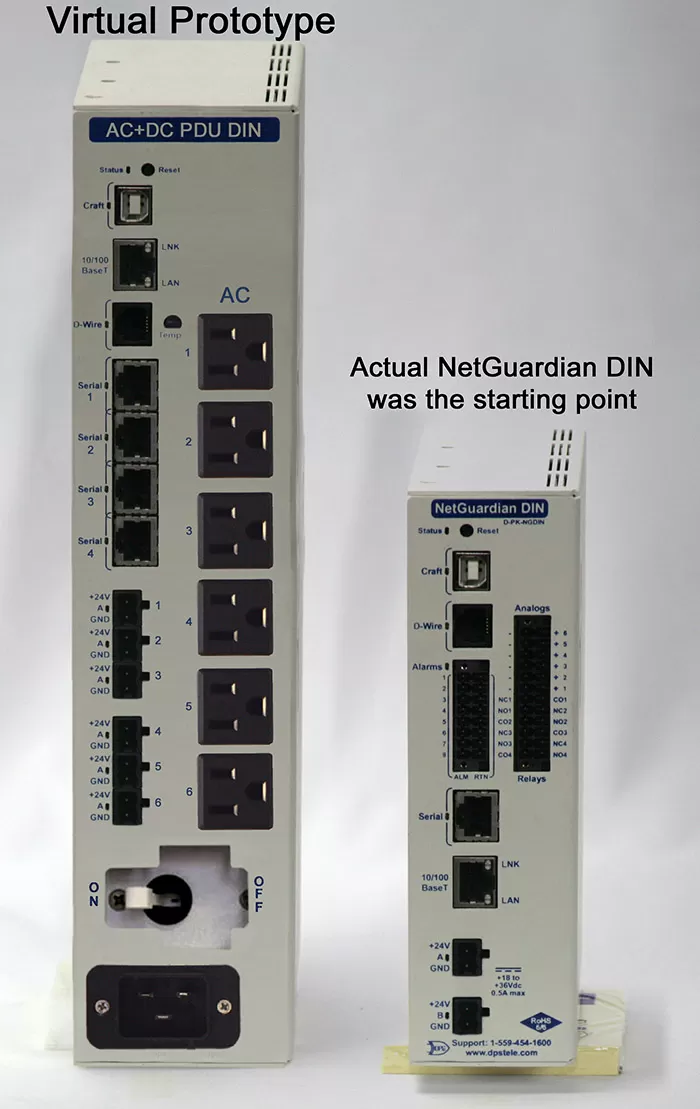
Because we were dealing with a DIN-mount device, my starting point was obvious: the NetGuardian DIN.
I kept a few of the universal elements, like RIA power plugs, USB port, and 10/100 LAN. I lifted them up to new layers so they wouldn't get wiped out - and could be repositioned later.
With the reusable elements preserved, I digitally scrubbed out the RTU I/O, since those wouldn't be needed.
Next, I expanded the physical chassis to suit the larger connectors required for an AC+DC PDU. In particular, the standard household AC plug format is much larger than simple pluggables or especially 50-pin amphenols.
I then added some new "silk screen" (dark blue text) to give appropriate labels to the new ports. The name I put in the top corner, "AC+DC PDU DIN", won't win any awards for creativity. It was enough to facilitate a discussion with my client.

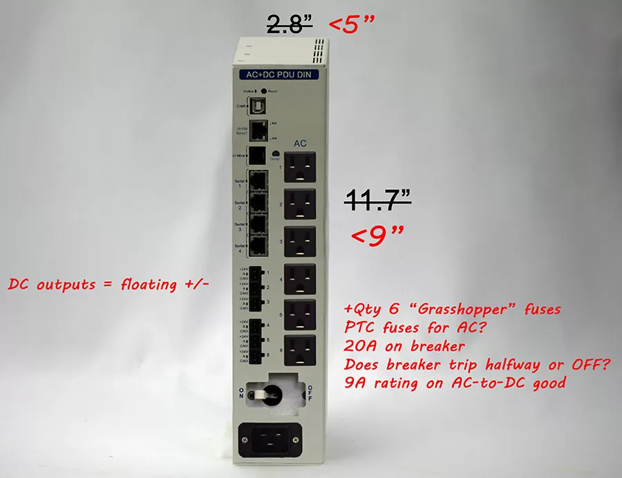
Overall, the design was looking pretty good. My estimate for the device height (based on an inches-per-pixel calculation), was 11.9". That was just barely within my 12" constraint to fit in the client's cabinets.
As usual, there was a moderate amount of "wow" floating around the online meeting where I shared my prototype. This type of digital photo manipulation is uncommon in the B2B telecom-equipment space. Many of us in this industry are more technical than artistic. I guess I've managed to straddle the line between both.
The positive reactions I get for a prototype are more about the quality of the visuals and the "seeing is believing" benefits of something photo-realistic. The design might not be perfect yet, but that determination is infinitely easier with the benefit of a good visual.
That was certainly the case in my power-utility PDU project. Nothing really major needed to change, but my clients clarified that they're really more concerned about height than width. It would be better if I could make more of square than a tall rectangle. That might also increase passive cooling, since 10A relays under heavy load can generate quite a bit of heat.
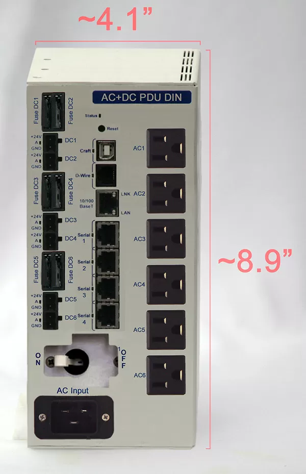
That request led me to this second revision:

As you can see, I didn't have to make many changes. I mostly just added a second circuit board to divide the connectors from the left into two columns. The AC plugs for the AC PDU section don't need a PCB (just internal wiring).
I did take the opportunity to use the additional front-panel space to add GMT fuses ("grasshopper fuses") for each of the 6 DC outputs. I really should have included those from the beginning, and suddenly I had enough physical space to place the fuse holders.
Although the second PCB and the fuses add some hardware expense, it's not a huge change to the overall project. This device will be a superior fit in the cabinet, which will yield benefits during every install and for years to come.
I knew I was doing something right when I called my client back to see what he (and the rest of the team) thought about my updated design and price quote. His response told me everything I needed to hear:
"We think this looks really good. We've actually also sent it to our eastern region for them to review it as well. I think they might also like to use it."
If you work on projects in telecom huts, power substations, trackside enclosures for railways, county radio sites, or another other remote location, you can benefit from a semi-custom device. It almost certainly won't be the one I've shown you here, but I'll follow this same process to build you whatever you need.
You just need to do one thing: tell me what you're trying to accomplish. I'll work with you to build that perfect-fit solution that we envision together.
Give me a call at 559-454-1600. You can also email me at sales@dpstele.com

Andrew Erickson
Andrew Erickson is an Application Engineer at DPS Telecom, a manufacturer of semi-custom remote alarm monitoring systems based in Fresno, California. Andrew brings more than 19 years of experience building site monitoring solutions, developing intuitive user interfaces and documentation, and opt...